Étape 6: Le capitaine plein contrôle code


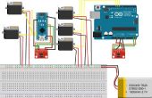
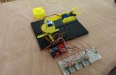
Code complet pour bras robotisé inclus ci-dessous.
Nous avons eu quelques problèmes avec le code que nous avons utilisé, mais puisque nous avons également eu quelques problèmes avec la tension qui, comme l’a expliqué à l’étape 5, nous avons eu un mal de tri à travers la plus grande partie de tout cela. Il est à noter que cette section de code ne contienne pas le code pour le capteur.
<pre><pre>#ifndef _stepLib_h_<br>#define _stepLib_h_ #include "Arduino.h" // define our stepper class class stepMotor { public: stepMotor(byte stepPin, byte dirPin); // our stepper object with variables stepPin and dirPin void step(unsigned int stepFreq); // our stepping function which takes as an input our stepping frequency private: unsigned long _time; // current time unsigned long _lastStepTime; // time at which we last stepped unsigned long _stepPeriod; // time between a half period - this is the same as our delay(X) of part 1 byte _stepPin; byte _dirPin; boolean _stepCycle; // defines if we are on the HIGH or LOW side of our step cycle }; #endif #include "Arduino.h" #include "stepLib.h" // used for declaring our motor and initializing it stepMotor::stepMotor(byte stepPin, byte dirPin) { _stepPin = stepPin; _dirPin = dirPin; // define our digital pins as output pinMode(_stepPin, OUTPUT); pinMode(_dirPin, OUTPUT); // initialize our digital pins to LOW digitalWrite(_stepPin, LOW); digitalWrite(_dirPin, LOW); _stepCycle = false; // this keeps track of which end of the step cycle we are on: high or low } // function responsible for driving our digital pins high/low at the proper frequency // input is the stepping frequency void stepMotor::step(unsigned int stepFreq) { _time = micros(); // get the current time _stepPeriod = 1000000 / stepFreq; // get our step period (in micro-seconds) from the user given step frequency; we lose a bit of accuracy here since we've defined _stepPeriod as an unsigned long instead of a float, but that's ok... // if the proper amount of time has passed, let's go ahead and proceed to the next half of our step cycle if (_time >= _lastStepTime + _stepPeriod) { digitalWrite(_stepPin, _stepCycle == true); // a compact way of writing either HIGH/LOW to our step pin based on where we are on our step cycle _stepCycle = !_stepCycle; // this simply flips our Boolean _lastStepTime = _time; // update the time we last stepped } } #include "stepLib.h" // define a constant value named stepPin and assign the value 8 to it - this value will not change during our code // this assumes digital pin 8 of your Arduino is attached to the step input of your driver #define stepPin 9 // define a constant value named dirPin and assign the value 8 to it - this value will not change during our code // this assumes digital pin 9 of your Arduino is attached to the step input of your driver #define dirPin 8 // instantiate a new object in our stepMotor library named slider // we are essentially declaring that we want to add a stepper motor named slider that has our defined stepPin and dirPin stepMotor slider(stepPin, dirPin); // setup() loop, the Arduino only runs through this once void setup() { } // loop() loop, the Arduino continuously cycles through this as fast as it can void loop() { slider.step(50); // step our motor at a given frequency (Hz) } #include "stepLib.h" // define our step pins # define sliderStep 9 # define panStep 11 # define tiltStep 7 // define our direction pins # define sliderDir 8 # define panDir 10 # define tiltDir 6 // instantiate a new object in our stepMotor library named slider // we are essentially declaring that we want to add a stepper motor named slider that has our defined stepPin and dirPin stepMotor slider(sliderStep, sliderDir); stepMotor pan(panStep, panDir); stepMotor tilt(tiltStep, tiltDir); // setup() loop, the Arduino only runs through this once void setup() { } // loop() loop, the Arduino continuously cycles through this as fast as it can void loop() { slider.step(50); // step our motor at a given frequency (Hz) pan.step(10); // step our motor at a given frequency (Hz) tilt.step(100); // step our motor at a given frequency (Hz) } #ifndef _stepLib_h_ #define _stepLib_h_ #include "Arduino.h" // define our stepper class class stepMotor { public: stepMotor(byte stepPin, byte dirPin); // our stepper object with variables stepPin and dirPin void step(unsigned int stepFreq); // our stepping function which takes as an input our stepping frequency void setDir(boolean dir); // function that allows us to set our direction of rotation private: unsigned long _time; // current time unsigned long _lastStepTime; // time at which we last stepped unsigned long _stepPeriod; // time between a half period - this is the same as our delay(X) of part 1 byte _stepPin; byte _dirPin; boolean _stepCycle; // defines if we are on the HIGH or LOW side of our step cycle }; #endif #include "Arduino.h" #include "stepLib.h" // used for declaring our motor and initializing it stepMotor::stepMotor(byte stepPin, byte dirPin) { _stepPin = stepPin; _dirPin = dirPin; // define our digital pins as output pinMode(_stepPin, OUTPUT); pinMode(_dirPin, OUTPUT); // initialize our digital pins to LOW digitalWrite(_stepPin, LOW); digitalWrite(_dirPin, LOW); _stepCycle = false; // this keeps track of which end of the step cycle we are on: high or low } // function responsible for driving our digital pins high/low at the proper frequency // input is the stepping frequency void stepMotor::step(unsigned int stepFreq) { _time = micros(); // get the current time _stepPeriod = 1000000 / stepFreq; // get our step period (in micro-seconds) from the user given step frequency; we lose a bit of accuracy here since we've defined _stepPeriod as an unsigned long instead of a float, but that's ok... // if the proper amount of time has passed, let's go ahead and proceed to the next half of our step cycle if (_time >= _lastStepTime + _stepPeriod) { digitalWrite(_stepPin, _stepCycle == true); // a compact way of writing either HIGH/LOW to our step pin based on where we are on our step cycle _stepCycle = !_stepCycle; // this simply flips our Boolean _lastStepTime = _time; // update the time we last stepped } } // given a boolean user input, set our direction of travel to that input void stepMotor::setDir(boolean dir) { digitalWrite(_dirPin, dir); } #include "stepLib.h" // define our step pins # define sliderStep 9 # define panStep 11 # define tiltStep 7 // define our direction pins # define sliderDir 8 # define panDir 10 # define tiltDir 6 // define the pins on which we've put our N.O. buttons #define button1 2 #define button2 3 // our motor step frequencies int sliderFreq = 300; int panFreq = 10; int tiltFreq = 100; // instantiate a new object in our stepMotor library named slider // we are essentially declaring that we want to add a stepper motor named slider that has our defined stepPin and dirPin stepMotor slider(sliderStep, sliderDir); stepMotor pan(panStep, panDir); stepMotor tilt(tiltStep, tiltDir); // setup() loop, the Arduino only runs through this once void setup() { // define our button pins as input pullup type - see http://arduino.cc/en/Tutorial/DigitalPins#.Uyphr4WN7q4 pinMode(button1, INPUT_PULLUP); pinMode(button2, INPUT_PULLUP); } // loop() loop, the Arduino continuously cycles through this as fast as it can void loop() { if (digitalRead(button1) == LOW && digitalRead(button2) == HIGH) { // if button1 is pressed and button2 is not pressed slider.setDir(true); pan.setDir(true); tilt.setDir(true); } else if (digitalRead(button1) == HIGH && digitalRead(button2) == LOW) { // if btton1 is not pressed and button2 is pressed slider.setDir(false); pan.setDir(false); tilt.setDir(false); } if (digitalRead(button1) == LOW || digitalRead(button2) == LOW) { // if either button is pressed slider.step(sliderFreq); // step our motor at a given frequency (Hz) pan.step(panFreq); // step our motor at a given frequency (Hz) tilt.step(tiltFreq); // step our motor at a given frequency (Hz) } if (digitalRead(button1) == LOW && digitalRead(button2) == LOW) { // if both buttons are pressed together sliderFreq += 10; panFreq += 10; tiltFreq += 10; delay(10); // delay just a short while otherwise the double button presses causes our frequency to increase too quickly (we need to allow for the user to release the buttons) } } #include "stepLib.h" // define our step pins # define sliderStep 9 # define panStep 11 # define tiltStep 7 // define our direction pins # define sliderDir 8 # define panDir 10 # define tiltDir 6 // define the pins on which we've put our N.O. buttons #define button1 2 #define button2 3 // define our joystick pins; NOTE we are using analog pins, not digital #define LRjoystickPin 27 // left-right joystick #define UDjoystickPin 28 // up-down joystick // our motor step frequencies int sliderFreq = 50; int panFreq = 300; int tiltFreq = 100; // other variables byte deadband = 50; // size of deadband, from joystick neutral position, in which we assume we are reading 0 unsigned int LRjoyValue = 0; unsigned int UDjoyValue = 0; // instantiate a new object in our stepMotor library named slider // we are essentially declaring that we want to add a stepper motor named slider that has our defined stepPin and dirPin stepMotor slider(sliderStep, sliderDir); stepMotor pan(panStep, panDir); stepMotor tilt(tiltStep, tiltDir); // setup() loop, the Arduino only runs through this once void setup() { // define our button pins as input pullup type - see http://arduino.cc/en/Tutorial/DigitalPins#.Uyphr4WN7q4 pinMode(button1, INPUT_PULLUP); pinMode(button2, INPUT_PULLUP); pinMode(LRjoystickPin, INPUT); pinMode(UDjoystickPin, INPUT); } // loop() loop, the Arduino continuously cycles through this as fast as it can void loop() { // read our joystick values and store them LRjoyValue = analogRead(LRjoystickPin); // acts just like digitalRead, but for analog pins UDjoyValue = analogRead(UDjoystickPin); // acts just like digitalRead, but for analog pins // control our pan with the LR joystick if (LRjoyValue > 512+ deadband) { // joystick is outside of deadband, move right pan.setDir(true); pan.step(panFreq); } else if (LRjoyValue < 512- deadband) { // joystick is outside of deadband, move left pan.setDir(false); pan.step(panFreq); } // control our tilt with the UD joystick if (UDjoyValue > 512 + deadband) { // joystick is outside of deadband, move up tilt.setDir(true); tilt.step(panFreq); } else if (UDjoyValue < 512 - deadband) { // joystick is outside of deadband, move down tilt.setDir(false); tilt.step(panFreq); } // control our slider stepper with the two buttons, just like we did previously if (digitalRead(button1) == LOW && digitalRead(button2) == HIGH) { // if button1 is pressed and button2 is not pressed slider.setDir(true); } else if (digitalRead(button1) == HIGH && digitalRead(button2) == LOW) { // if btton1 is not pressed and button2 is pressed slider.setDir(false); } if (digitalRead(button1) == LOW || digitalRead(button2) == LOW) { // if either button is pressed slider.step(sliderFreq); // step our motor at a given frequency (Hz) } }
